
Basic Aerodynamics
An airfoil, the cross-sectional shape of an aircraft wing, owes its design to the work of Daniel Bernoulli, another physicist, who discovered and described certain principles of fluid flow. The "fluid", of course, is air, the medium through which aircraft move and depend upon for their lift. Mr. Bernoulli discovered some fairly simple relationships between fluid velocity and pressure which are the fundamental basis for the design of wings. Note that the discussion here really only applies to subsonic flow, not the compressible flow found in the transonic and supersonic cases. If you remember the picture of the pipe with a narrowed center section through which air is flowing from your high school or college physics class, you may also remember that as the air flows through the center narrow section, its velocity increases and its (static) pressure decreases. In the illustration below, V2 > V1 and P1 > P2.
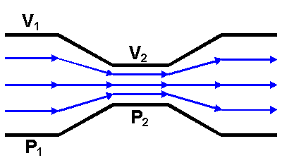
Without getting into a lot of math, Bernoulli found that the Total Pressure was a constant. The total pressure is defined as the static pressure plus the kinetic, or dynamic, pressure. This is really just another statement of the conservation of energy. This principle forms the basis for a wing to develop lift and also is the basis for the operation of an airspeed indicator.
Compare the illustration above to a simple wing cross-section:
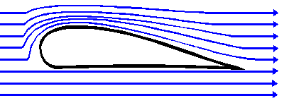
The airfoil is just an inside-out, asymmetrical version of the pipe used to demonstrate Bernoulli's Principle. The lift an airfoil generates is a reflection of the fact that the static pressure on the top surface of the wing is lower than that on the bottom surface. With a difference in static pressure, there is a net force in the direction of bottom to top.
The dynamic pressure of a gas flow is q = 1/2 d V2, where d is the density and V is the velocity. The Total Pressure, Pt ,can thus be expressed as:
Pt = Ps + q (where Ps is the static pressure)
We could also express the relationship as Ps = Pt - q
(I will have to be excused for the substitution of Latin characters where, traditionally, Greek characters would be used, because Hypertext Markup Language simply has no Greek characters in its repertoire. Density would normally be represented with the Greek rho.)
We can make some very broad simplifying assumptions and gain some insight into the operation of a wing, although even from the simple illustration above, it can be seen that the mathematics of the problem is already getting pretty messy. Let's just assume that the average flow velocity on the bottom surface of the wing is V1 and the average velocity on the top surface is V2. That being the case, using the second expression, above, the difference in static pressure across the wing would be:
Pdiff = (Pt - 1/2 d V12) - (Pt - 1/2 d V22)
Since Pt is a constant, the above expression reduces to:
Pdiff = 1/2 d (V22 - V12)
Since pressure is a force per unit area, the total lift is directly proportional to the wing area and is directly proportional to the air density. Once again, skipping a lot of the math, an airfoil can be characterized by an artifice called its Coefficient of Lift or CL. The Coefficient of Lift is not a constant, but varies with the Angle of Attack. Once in possession of the Coefficient of Lift, however, we can state the total lift of a wing as:
L = 1/2 d V2 S CL , where d is the air density, V is the velocity, and S is the total projected area of the wing
Let's define some terms before moving forward. First, Angle of Attack, is the angle between the wing chord and the relative wind. Oh great, define a new term with two more new terms! The chord of an airfoil is the straight line joining the ends of the mean camber line. OK, let's start at the beginning:
Mean Camber Line - The locus of points equidistant from the upper and
lower surfaces of an airfoil.
Chord - The straight line joining the ends of the mean camber line.
Flight Path Velocity - The speed and direction of the airfoil.
Relative Wind - Equal and opposite to the Flight Path Velocity
Angle of Attack - The angle between the relative wind and the chord of
the airfoil.
Some illustrations are in order.
The Mean Camber Line and Chord:
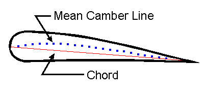
In this sketch, the Mean Camber Line is exaggerated in order to show the chord clearly.
The Chord, Relative Wind, and Angle of Attack:
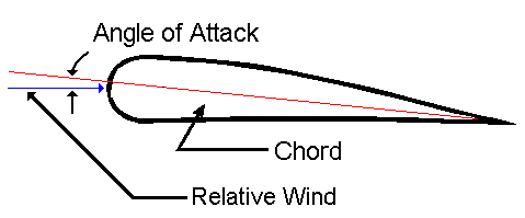
Now that the terms have been a little better described, a look at the Coefficient of Lift is in order. This is best done with another illustration:
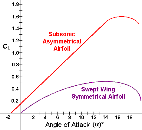
These Coefficient of Lift curves are shown for both a subsonic asymmetric airfoil and a swept wing symmetrical airfoil. What do these curves mean? As the angle of attack of a wing is increased, its coefficient of lift increases - up to a point. If the angle of attack is increased further, the rate of increase of the coefficient of lift is less, until finally it starts to actually decrease. Physically, the hook at the top of the curve is the onset of an aerodynamic stall - the point at which the airflow over the wings ceases to be a well-behaved laminar flow and the wing starts to lose lift. The basic lesson is that, although pilots often talk about stall "speed", a wing stalls at a predetermined angle of attack. That stall angle of attack is manufactured into the wing and nothing (well, almost nothing) changes it. A given wing can be stalled at any airspeed (if it is strong enough!). The reason I say "if it is strong enough" is that the way to stall a wing at high airspeed is simply to try to make it produce more lift than its coefficient of lift can provide. This is done by "pulling Gs"; for example, in a level turn at a bank angle approaching 90°. Practically speaking, most normal aircraft reach their structural limit before stalling the wing at high airspeed - this is not true of high performance aircraft, however. Referring again to the curves above, the line representing a subsonic asymmetrical airfoil is characteristic of a light aircraft like a Cessna 172. The Cessna 172 has a very abrupt and well-defined stall in which the nose of the aircraft drops, decreasing the wing's angle of attack and increasing its speed. The stall of a high performance aircraft, represented by the lower curve which is characteristic of an aircraft like the T-38, is much more insidious. It is possible to get a T-38 into a fully-developed stall in a level attitude with a very high sink rate (on the order of 20,000 ft/min).
Many aircraft provide tactile feedback to the pilot of an impending stall. As the airflow on the top surface of the wing becomes turbulent and that turbulence flows past the horizontal stabilizer, the pilot can feel the buffeting in the controls. Pilots refer to this as the "burble" or a "nibble". Some aircraft, particularly those with "T" tails, such as the C-141 or the Boeing 727 have their horizontal stabilizers deliberately positioned to avoid wing turbulence and provide no tactile feedback at all. These aircraft depend upon an angle of attack sensor and a "stick shaker" to warn the pilot of an impending stall condition. Ironically, neither of those aircraft provide a cockpit instrument which would allow the pilot to monitor the angle of attack.